FG40KK-5000G-90G-NG Incremental Encoder Solution
A custom compatible encoder solution can be provided for FG40KK-5000G-90G-NG in maintenance, retrofit, replacement, and upgrade projects. This model is an incremental encoder with dual terminal boxes, 5000 pulses per revolution, and a reference pulse with inverted signal. Typical production lead time: 15 working days. The engineering objective is to preserve high pulse-count continuity, split field wiring logic, reference pulse behavior, and original shaft-side installation fit so that field replacement can remain stable and practical.
Technical Overview of the FG40KK-5000G-90G-NG Encoder
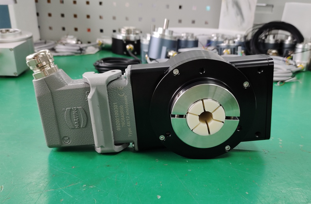
The FG40KK-5000G-90G-NG belongs to the FG40 square-wave incremental encoder platform. This coded version uses KK for two terminal boxes, 5000 pulses per revolution, and the NG option for a reference pulse with inverted signal. Electrically, the platform uses a push-pull line driver with short-circuit protection and integrated impedance adaptation for line resistances from 30 to 140 Ω, which makes it suitable for industrial pulse transmission where stable output behavior and serviceable field wiring are both required.
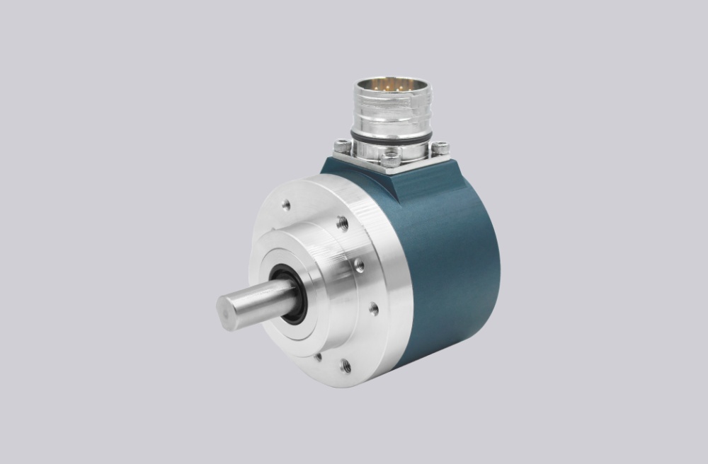
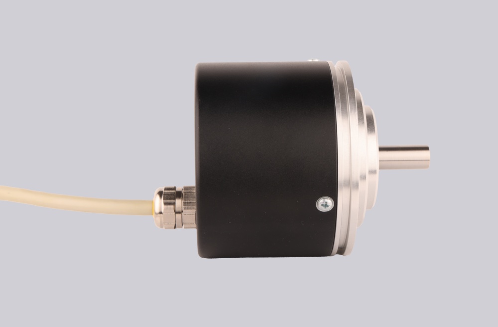
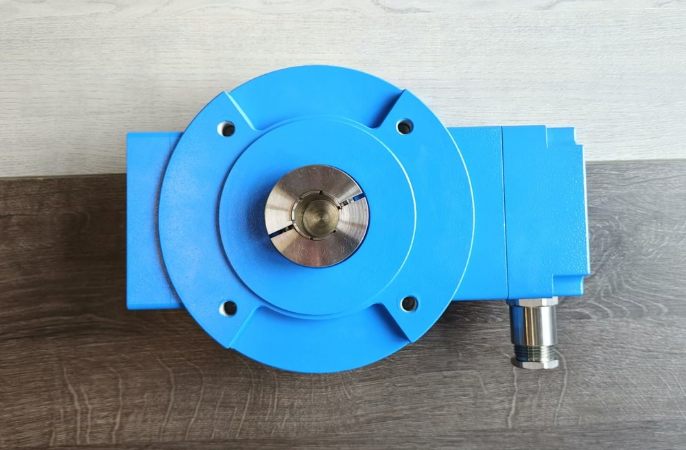
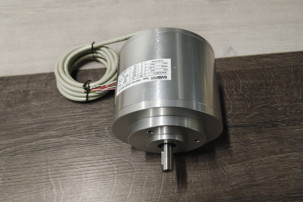
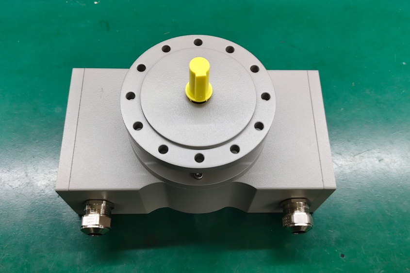
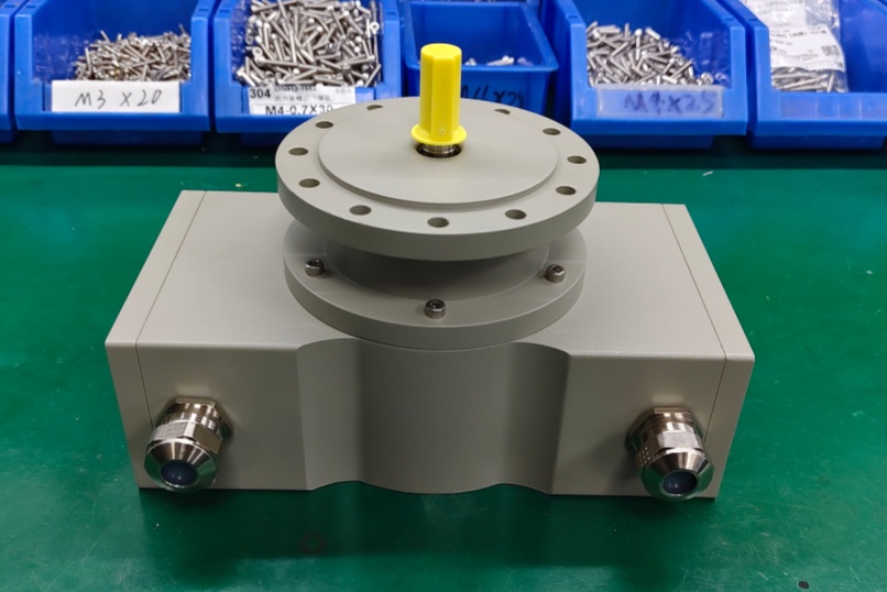
Mechanically, the encoder is based on the FG40 solid-shaft platform with standard shaft dimension 11j6 x 30 mm. The dual terminal-box arrangement makes this version particularly suitable for applications where pulse-output wiring and auxiliary signal routing should remain clearly separated and easy to maintain during service work. In practical retrofit projects, that wiring separation can be as important as the pulse count itself.
Industrial Integration Considerations
For this model, the main compatibility factor is the 5000 ppr pulse structure. This is not one of the most common basic industrial pulse counts, so it is often selected because the original machine, display ratio, controller scaling, or process calculation has already been built around that exact value. Replacing it with a nearby standard pulse count may create unnecessary reconfiguration in PLC logic, counter modules, or motion-monitoring systems. Preserving the original 5000 ppr structure is therefore usually the most stable engineering choice.
The NG reference pulse option is equally important where the machine uses the index signal for homing, synchronization, or defined reference-point confirmation. In those applications, replacement planning should preserve not only the main A/B pulse behavior, but also the original reference pulse arrangement and inverted index continuity.
From the mechanical side, the FG40 shaft platform should also remain aligned with the installed coupling arrangement. Shaft fit, coupling condition, and installation accuracy directly affect bearing life and long-term signal stability, so they should be confirmed during engineering review rather than assumed from housing dimensions alone.
Field Installation and Wiring Notes
For KK versions, the original terminal-box allocation should be checked carefully before replacement. In many field installations, the two terminal boxes are used to keep signal routing clearer and more serviceable. That allocation should remain unchanged so the installed harness logic does not need unnecessary redesign.
EMC practice should also remain aligned with the original installation. Encoder cables should be routed away from motors, inverters, contactors, solenoids, and brake wiring. Shield bonding should be maintained on both sides, and the grounding strap should remain short and correctly dimensioned. In higher pulse-count systems such as 5000 ppr applications, poor shielding or weak grounding is more likely to appear as unstable counting or unreliable index behavior.
Mechanical installation must remain force-free. Hammering during mounting is not permitted, and coupling misalignment should be avoided because it can increase radial load, shorten bearing life, and reduce signal quality. If the original installation uses a torsion-resistant zero-backlash coupling, that arrangement should be preserved during engineering review.
Custom Compatible Encoder Solution
A custom compatible encoder solution for FG40KK-5000G-90G-NG should preserve five engineering points: 5000 ppr pulse continuity, dual terminal-box wiring arrangement, NG reference pulse with inverted signal, push-pull electrical output behavior, and FG40 solid-shaft mechanical fit. This combination matters because successful field replacement depends on both maintaining the original counting behavior and preserving the installed field wiring concept.
From the electrical side, the compatible solution should remain aligned with the original supply range, pulse-output frequency expectations, and index-signal logic. From the mechanical side, it should preserve shaft size, shaft length, coupling compatibility, and terminal-box cable-entry layout. Where the installed application already uses pulse-based scaling or index-driven reference logic, those functions should be confirmed during engineering review before final release.
Custom Solution Photos
Lead Time and Custom Development
Typical production lead time: 15 working days.
For custom development, the main checkpoints should include shaft diameter, shaft length, coupling type, terminal-box allocation, pulse count continuity, reference pulse requirement, and controller-side frequency margin. EMC routing, shield termination method, and grounding continuity should also be checked so the final solution remains aligned with the installed field configuration.
Typical Technical Parameters
| Parameter | Specification |
|---|---|
| Encoder Type | Incremental encoder |
| Model | FG40KK-5000G-90G-NG |
| Output Type | Square-wave pulse output |
| Resolution | 5000 ppr |
| Output Stage | Push-pull line driver |
| Reference Signal | Reference pulse with inverted signal |
| Supply Voltage | 12 ... 30 V DC |
| No-Load Current | Approx. 50 mA at 24 V |
| Max. Output Current | 150 mA at 24 V |
| Max. Output Frequency | 200 kHz |
| Line Adaptation | Integrated impedance adaptation for 30 ... 140 Ω lines |
| Shaft Type | Solid shaft |
| Shaft Dimension | 11j6 x 30 mm |
| Connection Type | 2 terminal boxes |
| Protection Rating | IP65 standard |
| Operating Temperature | 0 ... +70 °C standard |
| Shock Resistance | 150 g |
| Vibration Resistance | 20 g |
| Max. Shaft Load | 100 N axial / 120 N radial |
| Max. Speed | Up to 6000 min⁻¹ depending on sealing |
Related Models
FG40KK-4096G-90G-NG Incremental Encoder Solution
FG40KK-10000G-90G-NG High Frequency Incremental Encoder Solution
FG40KK-16384G-90G-NG Incremental Encoder Custom Solution
FG40KK-2048G-90G-NG Incremental Encoder Engineering Solution