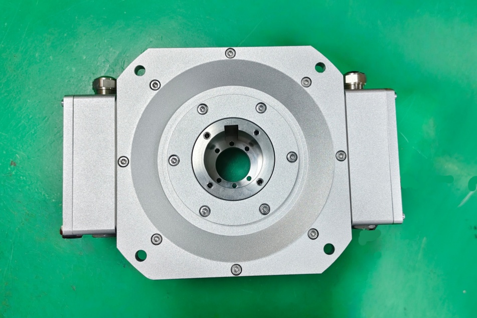
EncoderWorks develops the HOG161 DN 1024 I 75H7 custom compatible replacement solution around heavy-duty incremental feedback where 1024 PPR scaling, K1/K2/K0 channel logic, 9–30 VDC HTL output behavior, complementary inverted signals, terminal-box wiring, IP54 sealing, torque-arm restraint, and Ø75 mm through-hollow-shaft fit must remain matched to the installed counter and machine shaft. The failure boundary is not a fieldbus telegram or an absolute position word, but wrong HTL input level, missed high-speed edges, shifted zero-pulse timing, inverted-channel mismatch, shield noise, IP sealing error, torque-arm movement, and Ø75 bore-fit misalignment. Typical production lead time: 15 working days.
This model is used where the controller reads speed, direction, and reference position from K1 and K2 quadrature channels with K0 zero pulse. A compatible replacement must preserve the 1024 pulses per revolution, 90° phase relationship, 40–60% duty-cycle boundary, K0 reference-pulse behavior, 9–30 VDC HTL signal level, inverted K1/K2/K0 channels, terminal-box assignment, Ø75 H7 through-bore interface, housing ground path, and heavy-duty mounting boundary.
System Limits
The first system boundary is the I-type HTL counter interface. HOG 161 DN 1024 I 75H7 must be checked against the controller’s HTL input requirement, 9–30 VDC supply range, maximum input frequency, edge evaluation mode, expected K1/K2 direction logic, K0 zero-pulse width, inverted-channel use, cable length, and receiver noise margin. If the replacement is supplied as TTL, R-type TTL, another supply range, another PPR, another bore size, or without the required complementary channels, the counter may still detect motion while speed scaling, direction recognition, reference repeatability, or index capture becomes unreliable.
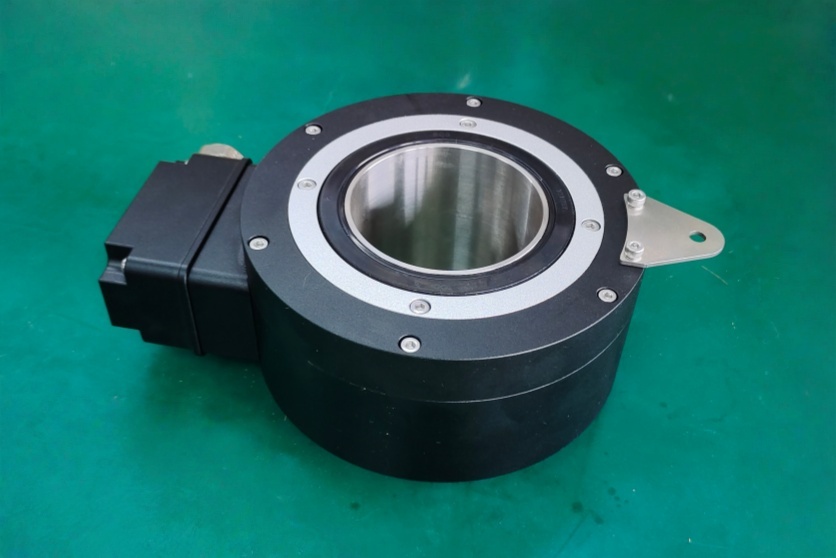
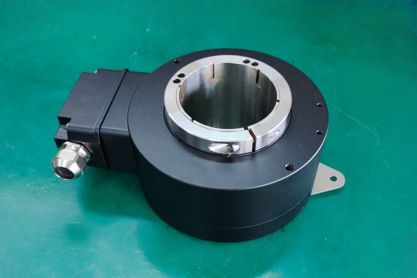
The second boundary is the terminal box, IP54 enclosure limit, torque arm, and Ø75 mm through-hollow-shaft installation. The +UB, 0V, K1, inverted K1, K2, inverted K2, K0, inverted K0, housing earth, shield path, cable gland, and terminal-box orientation must match the installed harness. A correct 1024 PPR HTL encoder can still fail if the shield is terminated through high impedance, the feedback cable runs beside brake or inverter wiring, the torque arm allows body movement, or the Ø75 H7 bore is installed on a shaft with runout, axial movement, or incorrect clearance. Corrosion exposure, sealing condition, shaft load, and grounding continuity should be checked together.
Wiring & Installation
Before replacement, confirm the complete installed model code, 1024 PPR requirement, I-type HTL supply and output level, K1/K2 phase relationship, K0 zero-pulse use, inverted-channel wiring, terminal-box layout, cable-entry direction, shield termination method, torque-arm length, Ø75 shaft fit, and machine-side tolerance. This I version should not be inferred from R-type TTL or 5 V TTL versions because the signal level, supply range, counter input threshold, cable-noise margin, and commissioning checks are different.
During installation, verify supply, 0V, K1, K2, K0, all inverted signals, housing earth, and shield continuity before powering the system. Keep the feedback cable away from motor, brake, SCR, and VFD wiring, and avoid using the shield as a load-carrying ground conductor. The Ø75 mm through hollow shaft must seat concentrically, and the torque arm must restrain encoder-body rotation without creating radial side load. Bore mismatch, eccentric seating, axial preload, or poor shield termination can appear as phase jitter, bearing stress, intermittent zero-pulse repeatability, or high-speed count loss.
Custom Compatible Solution
- Match 1024 PPR incremental feedback, K1/K2 quadrature, K0 zero pulse, I-type HTL output level, 9–30 VDC supply range, and inverted signal requirements
- Preserve terminal-box wiring, +UB / 0V reference, shield continuity, housing earth, cable-entry direction, and controller input compatibility
- Adapt the Ø75 H7 through hollow shaft, torque-arm restraint, light-metal housing boundary, corrosion exposure, and IP54 sealing requirement
- Review 120 kHz frequency margin, 90° phase tolerance, 40–60% duty cycle, zero-pulse timing, shaft load, vibration, grounding, and commissioning checks before shipment
Key Data
| Item | Data |
|---|---|
| Model | HOG 161 DN 1024 I 75H7 |
| Encoder type | Heavy-duty through-hollow-shaft incremental encoder |
| Feedback type | K1 / K2 quadrature with K0 zero pulse |
| Pulse count | 1024 PPR |
| Output signals | K1, K2, K0 with inverted signals |
| Output stage | I, HTL with inverted signals |
| Supply voltage | 9–30 VDC |
| Phase shift | 90° ±20° boundary |
| Duty cycle | 40–60% |
| Reference signal | K0 zero pulse, 90° width |
| Output frequency | ≤120 kHz, counter margin must be checked |
| Connection | Terminal box |
| Shaft interface | 75H7, Ø75 mm through hollow shaft |
| Protection rating | IP54 sealing boundary |
| Mechanical speed | ≤6000 rpm, application check required |
| Shaft load | ≤350 N axial / ≤500 N radial |
| Key replacement checks | I-type HTL level, 1024 PPR scaling, K1/K2 direction, K0 zero pulse, inverted channels, terminal mapping, IP54 sealing, shield grounding, torque arm, Ø75 bore fit |