


A custom compatible encoder solution can be provided for ATM90-PTG11x13 in maintenance, retrofit, replacement, and upgrade applications. This configuration is typically used in systems relying on PROFIBUS DP communication, multiturn absolute position feedback, and through-hollow shaft mounting with a bus adapter connection layout. Typical production lead time: 15 working days. During engineering review, key matching points include PROFIBUS DP communication behavior, 11 bit × 13 bit resolution structure, shaft interface, bus adapter topology, and installation continuity under existing field conditions.
Technical Overview of the ATM90-PTG11x13 Encoder
The ATM90-PTG11x13 is a multiturn absolute encoder built on a through-hollow shaft platform with PROFIBUS DP (DPV0) interface. The resolution configuration is 11 bit singleturn combined with 13 bit multiturn, providing extended turn-counting capability with moderate angular resolution per revolution.
This encoder platform uses magnetic scanning for singleturn detection and a mechanical gearbox for multiturn counting, allowing operation without battery dependency. The design supports long-term use with minimal maintenance requirements. The platform is also characterized by shallow installation depth and robust mechanical construction suitable for applications with vibration and mechanical load.
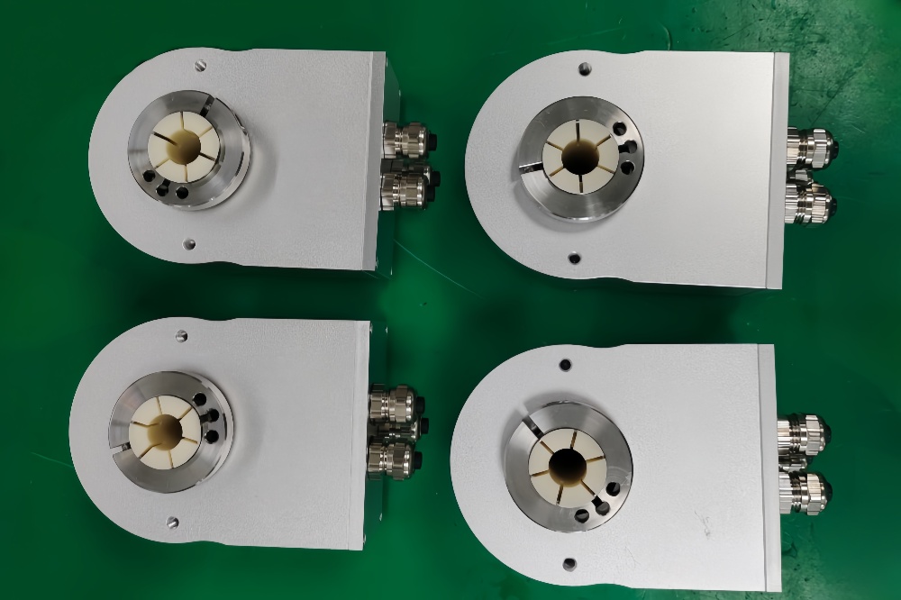
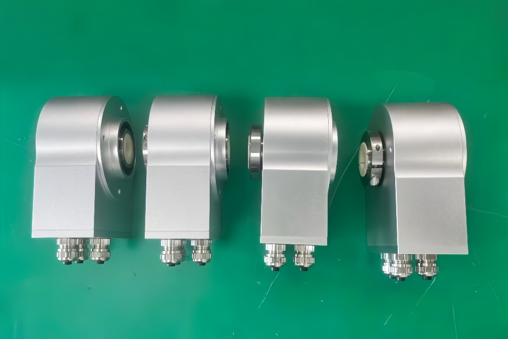
In this coded version, the connection type is a bus adapter layout with multiple radial connectors rather than a cable gland. This defines both wiring structure and installation constraints, especially in distributed PROFIBUS networks where bus continuity must be maintained.
Industrial Integration Considerations
The primary integration requirement is PROFIBUS communication continuity. A compatible solution should match the original PLC configuration, including DPV0 communication structure, transmission behavior, and parameterization logic. Since this platform supports programmable settings, correct configuration is required to ensure proper commissioning.
The second consideration is bus topology preservation. The bus adapter version typically supports bus in and bus out structure, meaning the encoder acts as part of a daisy-chain network. In retrofit work, this requires maintaining continuity of incoming and outgoing bus lines, correct node addressing, and proper termination strategy.
Resolution structure should also be aligned. The 11 bit × 13 bit configuration must match controller-side scaling and position tracking expectations to avoid inconsistencies in motion control systems.
Field Installation and Wiring Notes
For this model, field wiring should focus on the bus adapter connection layout. Compared to cable gland versions, the adapter provides structured connection points for PROFIBUS lines, typically supporting bus in and bus out continuity. During replacement, conductor mapping and connector assignment should be verified carefully to avoid network interruption.
Node addressing and termination must be checked before system startup. Incorrect address settings or termination configuration can affect the entire bus segment rather than a single encoder. In many field cases, communication instability is caused by incorrect wiring or connector handling during maintenance.
Cable routing and connector clearance should also be reviewed. The radial connector arrangement may require sufficient space for installation and service access. In compact machinery, limited clearance can affect connector engagement or lead to cable stress.
Mechanical installation should focus on the through-hollow shaft interface. Shaft diameter, insertion depth, and alignment should be verified before operation. Improper alignment or mounting stress may reduce service life, particularly in applications with vibration or dynamic load.
Custom Compatible Encoder Solution
A custom compatible encoder solution for ATM90-PTG11x13 typically focuses on:
- PROFIBUS DP communication and parameterization continuity
- 11 bit × 13 bit multiturn feedback structure
- Through-hollow shaft mechanical compatibility
- Bus adapter wiring with bus in / bus out continuity
- Stable operation under vibration and industrial conditions
These aspects should be confirmed during engineering review to ensure alignment with the original system.
Custom Solution Photos
Lead Time and Custom Development
Typical production lead time: 15 working days.
Custom development typically begins with confirmation of communication settings, bus topology, shaft dimensions, and installation conditions.
Typical Technical Parameters
| Parameter | Specification |
|---|---|
| Model | ATM90-PTG11x13 |
| Encoder Type | Multiturn absolute encoder |
| Shaft Type | Through-hollow shaft |
| Shaft Diameter | 12 mm |
| Interface | PROFIBUS DP (DPV0) |
| Resolution | 11 bit × 13 bit |
| Steps per Revolution | 2,048 |
| Number of Turns | 8,192 |
| Connection Type | Bus adapter, radial connectors |
| Parameterization | Programmable |
| Scanning Principle | Magnetic |
| Multiturn Principle | Mechanical gearbox, no battery |
| Installation Depth | Approx. 60 mm |
| Protection Class | IP65 |
| Operating Temperature | –20 °C to +80 °C |
Related Models
ATM90-PUG12x12 PROFIBUS Hollow Shaft Encoder
ATM90-PUG11x13 PROFIBUS Hollow Shaft Encoder Solution
ATM90-PXG13x13 PROFIBUS Hollow Shaft Encoder
ATM90-PXG13x11 High Singleturn PROFIBUS Encoder
ATM90-PTG12x12 PROFIBUS Encoder Solution


