We developed a custom solution for the POG10 D 500 I encoder, intended for heavy-duty drive systems where 500 PPR HTL incremental feedback must stay stable under shaft vibration, terminal-box wiring, high temperature, and EMC noise. This is a POG 10 D-output configuration, so it should be treated as K1 / K2 feedback only, not a DN version with K0 zero pulse.
Typical production lead time: 15 working days.
Model reading is direct:
- D = K1, K2 output signals
- 500 = 500 pulses per revolution
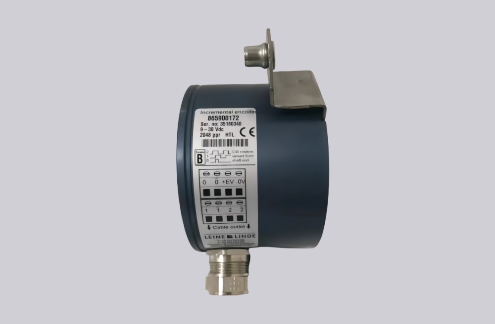
- I = 9–30 VDC, HTL output with inverted signals
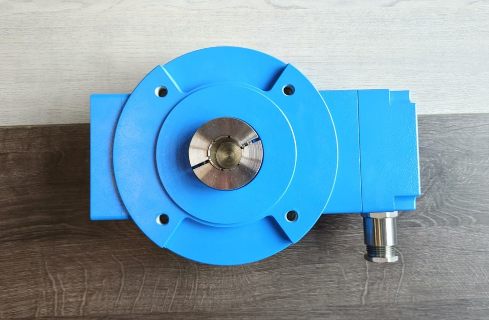
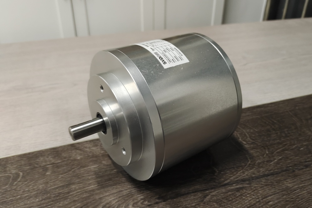
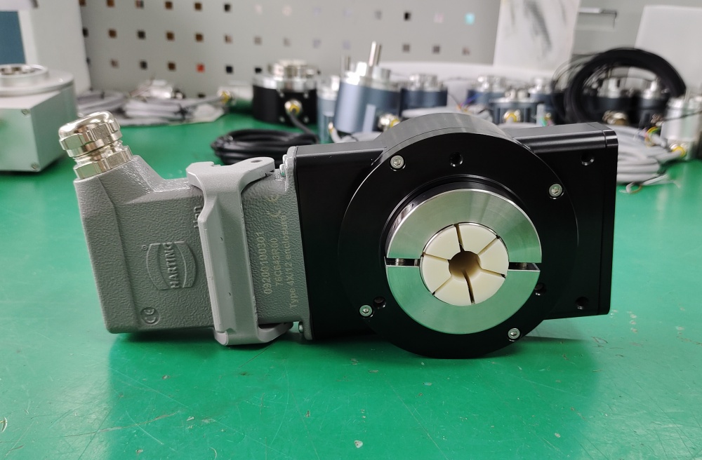
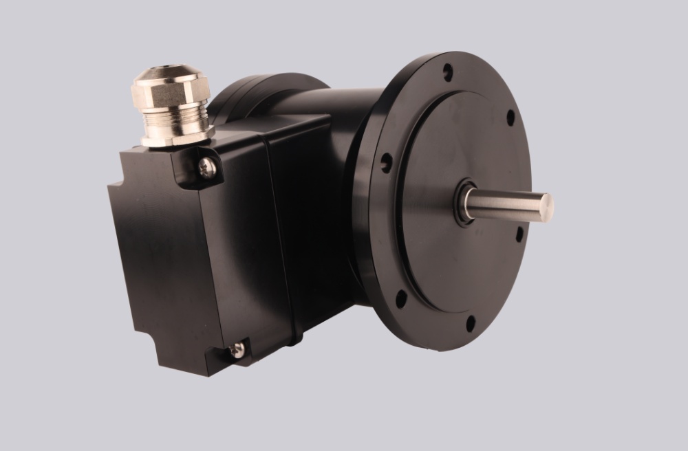
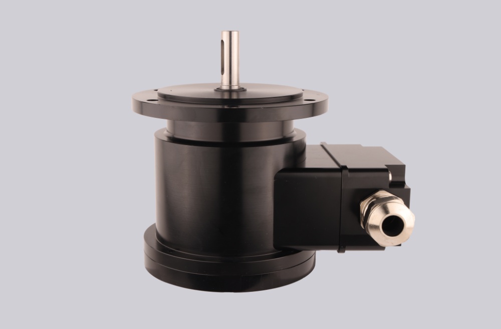
- POG10 = Ø11 mm shaft, EURO flange B10, terminal-box heavy-duty encoder body
At 500 PPR, the weak point is rarely pulse density. The first instability normally appears at terminal grounding, shield continuity, coupling torsion, or K1/K2 phase interpretation.
Where the System Fails First
The encoder allows ≤120 kHz output frequency, but at 500 PPR the controller is usually not the first limitation. Field failures more often come from poor shield termination, loose terminal-box wiring, motor-cable coupling noise, or rigid shaft coupling. The signal may still look present, but the counter no longer receives clean and repeatable HTL edges.
Typical failure points:
- Poor terminal grounding → false HTL edges
- Shield interruption → unstable speed feedback
- Loose terminal wiring → intermittent counting
- Wrong K1/K2 phase reading → reversed direction
- Rigid coupling → torsional shock into the Ø11 mm shaft
Because this is a D version, there is no K0 reference pulse. Do not use it where index referencing is required unless the machine has a separate home signal.
Mechanical Boundary
POG10 is built for heavy-duty shaft feedback: ≤300 N axial load, ≤450 N radial load, IP66 protection, 20 g vibration, 200 g shock, and -40 °C to +100 °C operating temperature. Those margins help only when shaft alignment and coupling selection are controlled. In heavy drives, torsional vibration usually becomes a pulse-quality problem before bearing damage is visible.
Installation Notes
- Keep the model format as POG10 D 500 I
- Do not add K0 logic; D = K1 / K2 only
- Keep terminal-box grounding continuous
- Separate encoder wiring from inverter and motor power cables
- Verify K1 / K2 phase direction before startup
- Use a flexible coupling suitable for Ø11 mm shaft
- Check shielding and grounding before replacing the encoder
Key Data
- Model: POG10 D 500 I
- Type: Heavy-duty incremental encoder
- Resolution: 500 PPR
- Output: HTL with inverted signals
- Signals: K1, K2 + inverted
- Supply voltage: 9–30 VDC
- Output frequency: ≤120 kHz
- Shaft: Ø11 mm stainless steel
- Flange: EURO flange B10
- Protection: IP66
- Operating temperature: -40 °C to +100 °C
- Optional temperature range: -50 °C to +100 °C
- Shaft load: ≤300 N axial / ≤450 N radial
- Vibration: 20 g, 10–2000 Hz
- Shock: 200 g, 6 ms
- Connection: Terminal box
- Weight: Approx. 1.9 kg