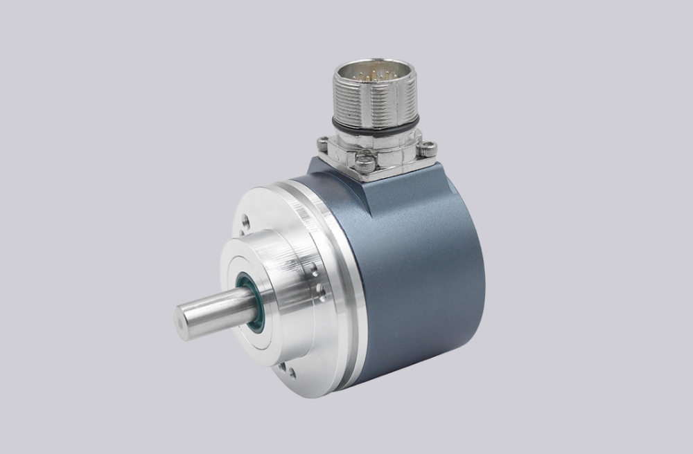
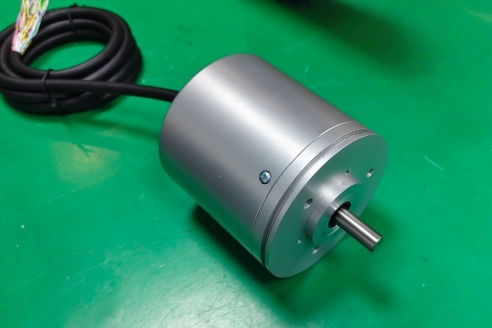
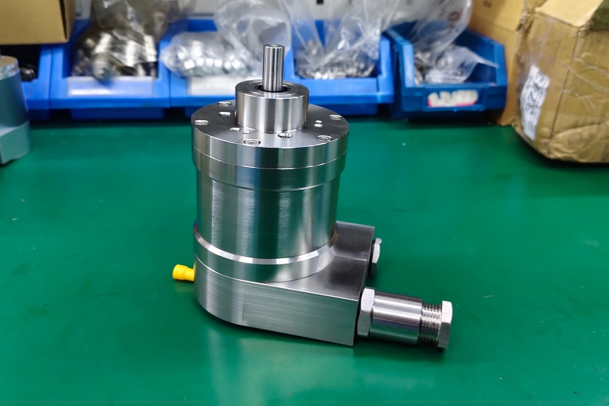
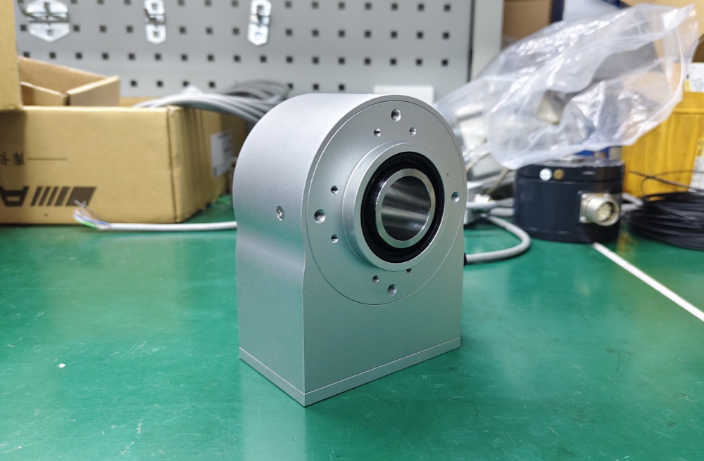
EncoderWorks provides custom compatible explosion-proof parallel absolute encoder replacement solutions for hazardous-area retrofit projects where bit output structure, connector wiring, reinforced housing, cable sealing, mechanical fit, and grounding must match the original installation. Replacement failure can occur when the parallel data length, bit order, output logic, counting direction, latch behavior, hazardous-area boundary, connector pinout, or shield grounding differs from the original encoder. Typical production lead time: 15 working days.
Explosion-proof parallel absolute encoders are used where direct absolute position feedback is required near flammable gases, vapors, combustible dust, heavy contamination, or harsh industrial process equipment. These installations are common in petrochemical equipment, chemical process machinery, mining systems, oil and gas handling equipment, hazardous-area conveyors, and heavy industrial automation. In these environments, encoder replacement should be reviewed as a signal, mechanical, and installation-safety problem rather than as a simple product match.
Parallel Signal Matching Limits
Parallel absolute encoders transmit position data through multiple output lines simultaneously. In replacement projects, the controller may expect a fixed number of bits, defined bit order, output logic level, code format, latch behavior, and counting direction. If the replacement encoder sends a different data width or uses a different binary / Gray code structure, the control system may read shifted values, unstable position data, or an incorrect zero reference.
Output behavior must also match the input module. Some legacy systems require a specific voltage level, active logic state, strobe or latch function, or wiring sequence across the controller terminals. A custom compatible explosion-proof parallel absolute encoder solution should confirm data length, output format, bit assignment, latch or enable function, zero-position behavior, and controller input requirements before production.
Explosion-Proof Housing and Mechanical Compatibility
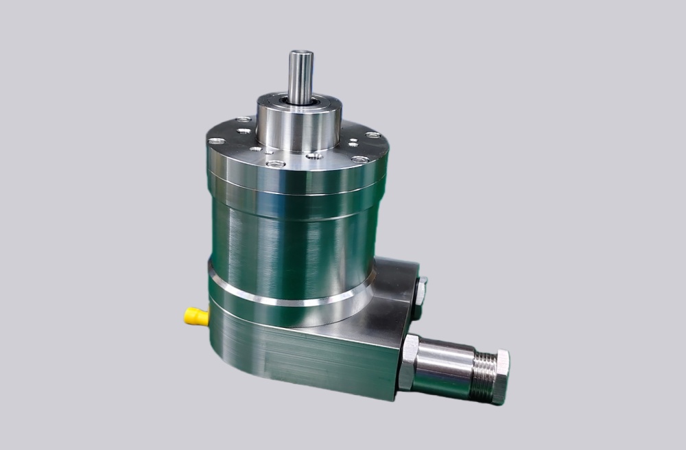
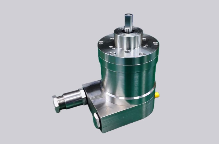
Explosion-proof encoder replacement is not only about choosing the same signal interface. The reinforced housing, sealing method, flange interface, cable outlet, connector protection, and hazardous-area installation boundary must remain suitable for the original environment. If the original installation uses a sealed cable entry, reinforced enclosure, heavy-duty connector, or specific mounting method, these details should be reviewed before selecting a replacement.
Mechanical compatibility should include shaft diameter, flange pattern, mounting depth, coupling space, solid-shaft or hollow-shaft interface, cable outlet direction, and available clearance around the machine. Excessive vibration, shaft misalignment, axial load, radial load, cable stress, or housing interference may reduce bearing life and affect signal stability. For hazardous-area equipment, poor mechanical fit or incorrect cable sealing may also create installation reliability risks.
Wiring, Shielding, and Input Stability
Explosion-proof parallel absolute encoder wiring normally includes power supply, multiple data lines, common reference, shield connection, and sometimes latch, enable, or direction-related lines. Because many conductors pass through a protected cable outlet or sealed connector, the pinout and cable definition must be reviewed carefully before production. A single swapped bit line can cause a position value that appears partly correct but fails across the full travel range.
A stable replacement should confirm connector pinout, data-line order, output voltage level, shield continuity, grounding method, cable sealing, and controller input compatibility. In hazardous industrial sites, cables may pass near motors, drives, pumps, contactors, braking circuits, or high-current switching devices. Poor shielding or grounding can create unstable input states, random bit changes, intermittent faults, or position errors during machine motion.
When Replacement Fails
Explosion-proof parallel absolute encoder replacement often fails when the encoder is treated as a normal dimensional replacement instead of a complete signal and hazardous-area installation system. Typical failure points include wrong data width, reversed bit order, binary / Gray code mismatch, different output logic, missing latch behavior, zero-position offset, connector mismatch, swapped data lines, poor shield grounding, and cable sealing mismatch.
Some failures do not appear during static installation checks. They may appear only after the machine moves through a larger position range, when multiple data lines change state at the same time and noise enters the wiring path. In hazardous-area applications, this risk is higher because the enclosure, cable outlet, and grounding path must support both signal integrity and installation reliability.
Replacement and Retrofit Considerations
An explosion-proof parallel absolute encoder should not be replaced only by checking resolution, interface name, or housing diameter. The same parallel output description does not guarantee the same bit order, code format, output voltage, latch behavior, or controller input compatibility. The same mechanical size also does not guarantee that the explosion-proof housing boundary, flange position, or cable sealing method will match the original equipment.
For older machines, the original encoder model may no longer be available, or the machine builder may have used a customized cable harness or protected connector layout. EncoderWorks can evaluate nameplate data, mechanical drawings, connector photos, wiring diagrams, hazardous-area installation details, and controller input requirements to define a custom compatible replacement path.
EncoderWorks Custom Compatible Solution
EncoderWorks supports custom compatible explosion-proof parallel absolute encoder solutions for replacement and retrofit applications.
- Match parallel data width, bit order, binary / Gray code format, output logic, latch behavior, and counting direction according to controller requirements.
- Confirm explosion-proof housing boundary, shaft interface, flange pattern, mounting depth, cable sealing method, and connector direction before production.
- Adapt connector pinout, cable length, data-line order, shielding, grounding method, cable outlet, and supply voltage to existing machine wiring.
- Review failure boundaries such as wrong bit mapping, unstable input states, direction reversal, zero-position offset, cable sealing mismatch, bearing load, cable strain, and noise interference.
Related Solutions
Product Selection
For product configuration and model selection, use the corresponding SIVIDI selection page.
Configure on SIVIDI:Parallel I/O Explosion-Proof Absolute Encoder SAS/M78