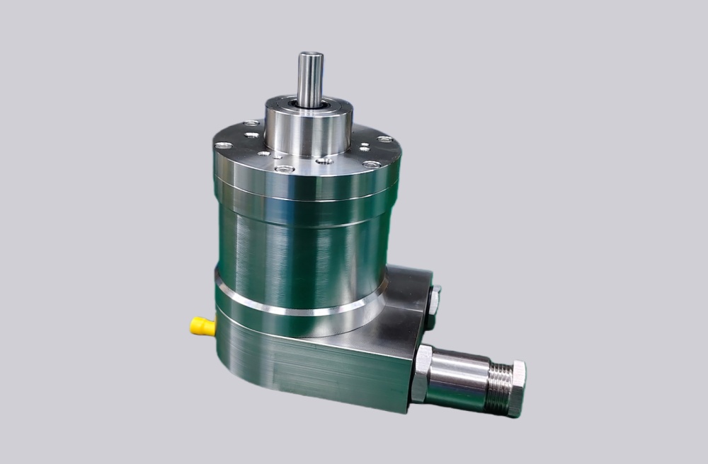
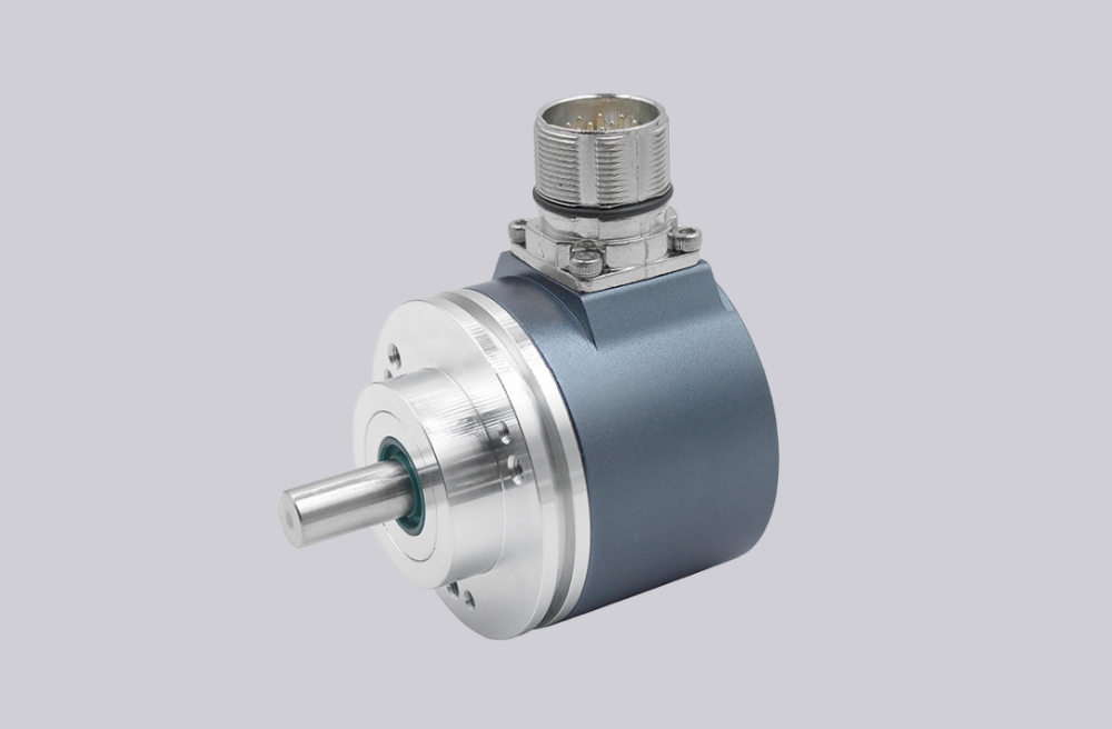
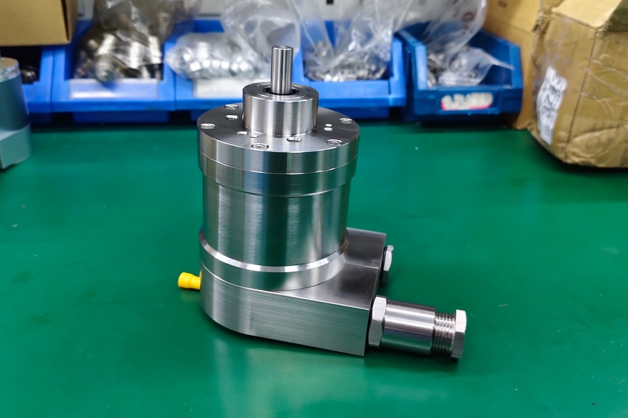
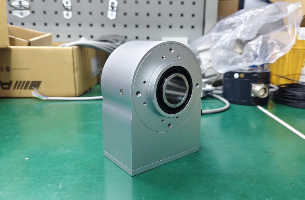
EncoderWorks provides custom compatible hollow-shaft PROFIBUS DP absolute encoder replacement solutions for retrofit projects where through-shaft fit, torque restraint, fieldbus configuration, GSD compatibility, connector layout, and bus shielding must match the original machine. Replacement failure can occur when shaft diameter, clamp stability, station address, cyclic data mapping, counting direction, connector pinout, bus termination, or cable grounding differs from the original encoder. Typical production lead time: 15 working days.
Hollow-shaft PROFIBUS DP absolute encoders are used where direct shaft mounting is preferred and the machine shaft must pass through or into the encoder body. This structure can reduce axial installation length, remove intermediate couplings, and simplify compact automation layouts. However, a hollow-shaft PROFIBUS DP encoder replacement should be reviewed as a mechanical, fieldbus, and installation system rather than as a simple bore-size and protocol match.
PROFIBUS DP Communication Matching Limits
PROFIBUS DP encoders exchange cyclic position data with PLC systems through a deterministic fieldbus network. In replacement projects, the PLC may expect a fixed station address, GSD file, module structure, input data length, byte order, diagnostic behavior, and position data format. If the replacement encoder uses a different configuration model, the controller may show device errors or read incorrect position values.
Data mapping is especially important during retrofit work. Some systems read only absolute position, while others use multi-turn data, status bits, diagnostic data, or preset-related information. A custom compatible hollow-shaft PROFIBUS DP encoder solution should confirm station addressing, GSD compatibility, cyclic data length, data order, counting direction, zero-position behavior, and controller commissioning requirements before production.
Hollow-Shaft Mechanical Compatibility
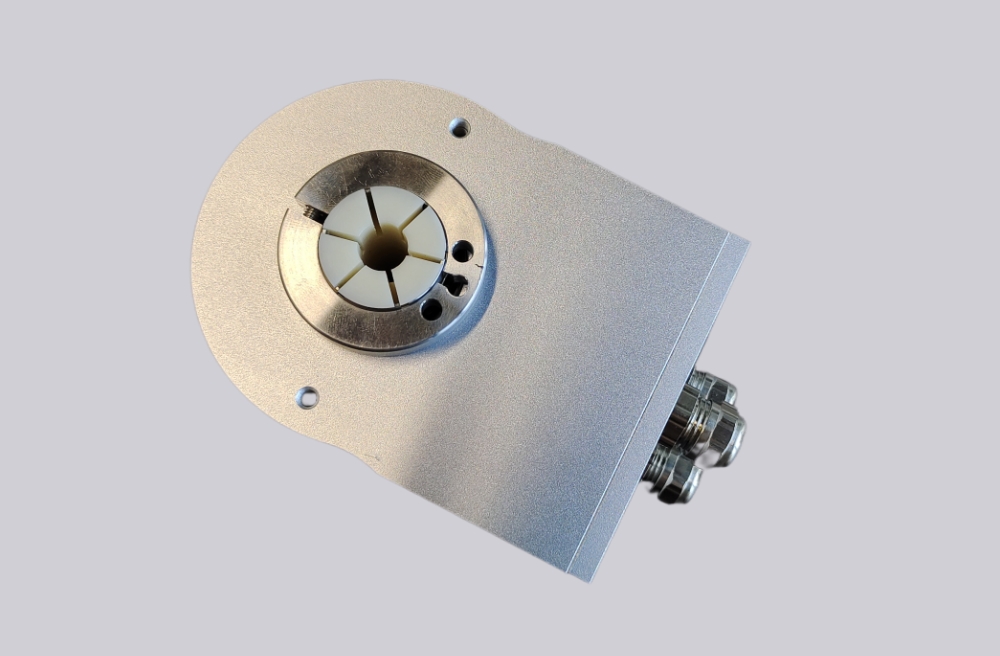
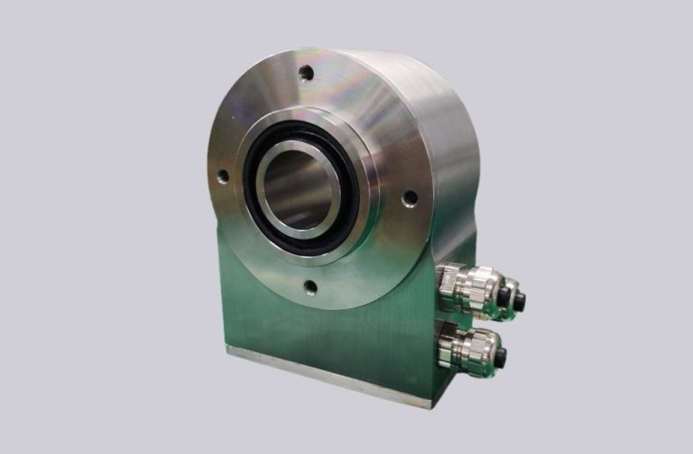
The key boundary of a hollow-shaft encoder replacement is the shaft interface. Shaft diameter, shaft length inside the encoder, clamping method, torque support, mounting depth, cable outlet direction, and available installation space must be checked before production. A through-shaft layout can simplify installation, but it also places higher demand on concentricity, clamping balance, and axial positioning.
Mechanical mismatch can cause more than installation difficulty. Excessive radial load, axial preload, shaft runout, uneven clamping force, torque arm stress, or housing interference may shorten bearing life and create unstable feedback. In retrofit projects, EncoderWorks checks the hollow-shaft fit together with the flange, bracket, torque restraint, connector direction, PROFIBUS cable exit, and installation space around the machine shaft.
PROFIBUS Wiring, Shielding, and Noise Control
Hollow-shaft PROFIBUS DP encoder wiring normally includes power supply, fieldbus communication lines, shield continuity, termination, and grounding. In compact machines, encoder cables may run near servo drives, motors, braking circuits, or high-current switching devices. If bus shielding, termination, or grounding is not handled correctly, the control system may show communication alarms, intermittent bus errors, diagnostic faults, or unstable feedback during acceleration and deceleration.
A stable replacement should confirm connector type, cable direction, bus polarity, termination position, shield continuity, grounding method, power supply range, and bus topology. Station address, PLC hardware configuration, GSD module selection, and diagnostic access should also be checked before commissioning. If the original encoder uses a specific connector orientation, cable length, or outlet direction, these details should be matched to avoid cabinet rewiring or mechanical interference.
When Replacement Fails
Hollow-shaft PROFIBUS DP encoder replacement often fails at the combined mechanical and fieldbus boundary. Typical failure points include shaft diameter mismatch, bearing preload, clamp slippage, torque support stress, wrong PROFIBUS station address, incompatible GSD module, different cyclic data length, reversed counting direction, zero-position offset, connector mismatch, missing termination, and noise entering through the shield path.
These issues may not appear when the encoder is only tested on the bench. They often appear after installation, when shaft runout, vibration, cable movement, bus topology, drive noise, PLC cycle timing, and mechanical load act together. For this reason, hollow-shaft PROFIBUS DP replacement should be evaluated before production using both communication requirements and installation dimensions.
Replacement and Retrofit Considerations
A hollow-shaft PROFIBUS DP absolute encoder should not be selected only by checking the bore size and protocol name. The same bore size does not guarantee the same clamping depth, torque support position, cable exit direction, or mechanical load capacity. The same PROFIBUS DP label also does not guarantee the same GSD configuration, data module, diagnostic behavior, or controller reading logic.
For older equipment, the original encoder model may no longer be available, or the machine builder may have used a customized mounting and PLC configuration. EncoderWorks can review nameplate data, shaft drawings, installation photos, connector information, GSD requirements, controller screenshots, and cable routing conditions to define a custom compatible replacement path.
EncoderWorks Custom Compatible Solution
EncoderWorks supports custom compatible hollow-shaft PROFIBUS DP absolute encoder solutions for replacement and retrofit applications.
- Match PROFIBUS DP station address, GSD configuration, cyclic data length, module structure, data mapping, diagnostics, and output behavior according to PLC requirements.
- Confirm hollow-shaft diameter, clamping depth, mounting space, torque support, flange boundary, connector direction, and cable outlet direction before production.
- Adapt connector layout, cable length, bus termination, shield continuity, grounding method, supply voltage, and fieldbus installation boundary to existing machine wiring.
- Review failure boundaries such as no PLC communication, wrong data module, unstable bus connection, direction reversal, zero-position offset, clamp slippage, bearing preload, shaft runout, and noise interference.
Related Solutions
Product Selection
For product configuration and model selection, use the corresponding SIVIDI selection page.
Configure on SIVIDI:Profibus-DP Hollow Shaft Absolute Encoder SAS/M90